We offer a varieties of wheel alignment machine to cater to different types of vehicles and requirements. Our range of machines includes 3D wheel alignment machines, laser wheel alignment machines, and computerized wheel alignment machines.
The Benchmarks Of Our Wheel Alignment Machines.
Efficiency 92.4%
Accuracy99.9%
Quality Rating96.03%
#Wheel Alignment Machine
There are different types of wheel alignment machine available.
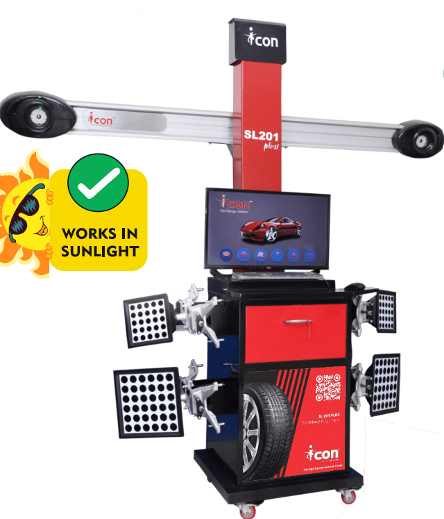
The SL-200 Series 3D Wheel Alignment Machine by Icon Autocraft Pvt. Ltd. is a cutting-edge solution designed for precision, efficiency, and ease of use. Engineered with 140+ high-intensity LEDs and the latest technology, it delivers superior accuracy and enhanced visibility, ensuring seamless alignment adjustments. Its user-friendly software simplifies operations, making it ideal for workshops aiming to improve productivity. Built with a durable and robust design, the SL-200 guarantees long-term reliability while offering a cost-effective solution for professional alignment services. Experience next-level performance and precision with the SL-200, the perfect choice for modern automotive workshops.
ICON 3D wheel alignment machine is stable, accurate, low cost, and easy-to-maintain 2 camera system wheel aligner. Specially designed for clients who need to expand their business with high performance equipment requirement. This product has outstanding & unique feature and the most advanced technology to ensure the growth of your garage.
Live camera view guides the technician to correct camera position.
All cameras are calibrated precisely by professional engineers so that no repeated calibration is required afterwards and the machine gives precise result immediately after installation.
User friendly interface. Even a less qualified technical operator can complete the wheel alignment with the help of colour coding.
Very good repeatability of the result.
The target is made of special material that is anti-corrosive, impact resistant and without electronic error.
Complete Indian and Imported car data base.
Automatic saving of wheel Alignment results.
Customer address in print out and data edit function.
Push pull compensation for Run out / Set back / Thrust Angle.
Our 3D wheel aligner is stable, accurate, low cost, and easy-to-maintain 2 camera system wheel aligner. Specially designed for clients who need to expand their business with high performance equipment requirement. This product has outstanding & unique feature and the most advanced technology to ensure the growth of your garage.
Live camera view guides the technician to correct camera position.
All cameras are calibrated precisely by professional engineers so that no repeated calibration is required afterwards and the machine gives precise result immediately after installation.
User friendly interface. Even a less qualified technical operator can complete the wheel alignment with the help of colour coding.
Very good repeatability of the result.
The target is made of special material that is anti-corrosive, impact resistant and without electronic error.
Complete Indian and Imported car data base.
Automatic saving of wheel Alignment results.
Customer address in print out and data edit function.
Push pull compensation for Run out / Set back / Thrust Angle.
ICON 3D wheel alignment machine is stable, accurate, low cost, and easy-to-maintain 2 camera system wheel aligner. Specially designed for clients who need to expand their business with high performance equipment requirement. This product has outstanding & unique feature and the most advanced technology to ensure the growth of your garage.
• It allows taking measurements on heavy duty vehicles with the wheelbase up to 16 meters • 4 Digital HD video cameras • Machine vision system housing are vertical posts equipped with high – precision network cameras with high -quality matrices • Machine vision system automatically recognizes the targets that are installed on the wheels of the vehicle and the position of the probe target. After that it calculates their geometrical position in space to high precision. • Compact and easy Targets. • One Targe for each wheel. • Easy to handle. • No need to calibrate targets • Self-centering wheel adapters with the mobile central part fit 12″-24″ wheel disk and are compatible with motorcars and trucks. • Remote control allows you to control your pc from the distance up to 10 meters.
MAIN ADVANTAGES:
Icon IA 700 Truck allows measuring trucks with the wheelbase up to
16 meters.
Drive-through is allowed.
If it is necessary to measure control points of the frame near the front bumper, the distance from the cameras to the front turn tables should be not less than 3000mm.
ICON 3D wheel aligner is stable, accurate, low cost, and easy-to-maintain 2 camera system wheel aligner. Specially designed for clients who need to expand their business with high performance equipment requirement. This product has outstanding & unique feature and the most advanced technology to ensure the growth of your garage.
Number of cameras :4 immovable cameras. Camera type : 2 video cameras 1.3MPix and 2 video cameras 5MPix Mounting type : Floor-mount. Two low pillars. Cabinet type : T – series Applicability : Pit distance from cameras to the center of front turn
This single content merges all the information provided about 3D wheel alignment machines, computer vision optimization, and the ICON Encore Gold 3D Wheel Alignment Machine Mannual.
PART A: 3D Wheel Alignment Machines – The Future of Precision Automotive Servicing
Why 3D Wheel Alignment Matters
Unmatched Precision & Accuracy
Traditional laser and CCD machines can do a decent job, but 3D systems provide a level of accuracy down to mere minutes of angular measurement. This precision ensures minimal tire wear, optimal handling, and enhanced safety.
Speed & Efficiency
3D alignment machines significantly reduce the time spent on calibrations and measurements. Real-time data readings allow technicians to make quick adjustments, increasing the total number of vehicles serviced per day.
Enhanced Profitability
With faster turnaround times and more accurate results, shops can handle more customers and reduce comebacks. This improves both your revenue stream and customer satisfaction.
Better Customer Satisfaction & Retention
Modern vehicles often come with performance-oriented suspensions and advanced driver-assist systems. Proper alignment is crucial for maintaining these features. Providing top-tier alignment services helps earn your customers’ trust and loyalty.
Long-Term ROI
Investing in a 3D wheel alignment machine offers a robust return on investment. Reduced labor time, fewer comebacks, and increased workshop throughput quickly offset the initial costs.
Key Features of a 3D Wheel Alignment Machine
High-Resolution Cameras
Utilizes industrial-grade CMOS sensors for real-time imaging and data capture.
Intelligent Target Plates
Passive, strong-aluminum targets built to withstand shop environments without compromising accuracy.
Automated Alignment Reports
Print or share digital reports for added transparency with customers.
Advanced Algorithms
Leverages stereoscopic vision and proprietary calibration methods to reduce measurement error to mere minutes of angle.
Types of Wheel Alignment Machines
Wheel alignment is a crucial aspect of vehicle maintenance, directly affecting handling, tire wear, fuel efficiency, and overall driving comfort. As vehicles become more technologically advanced, so do the tools required to maintain them. Automotive workshops and service centers must invest in the right wheel alignment machine to provide accurate, efficient, and reliable alignment services.
Selecting the right alignment system depends on factors such as the type of vehicles serviced, workshop size, required precision, and budget. Below is an in-depth look at different types of wheel alignment machines and their applications.
1. Hydraulic Wheel Alignment Machine
Best suited for: Heavy-duty vehicle workshops, fleet management centers, and commercial vehicle maintenance facilities.
Hydraulic wheel alignment machines are designed to handle the extreme weight and size of trucks, buses, and other large commercial vehicles. These systems incorporate hydraulic lifting mechanisms to position and align wheels efficiently.
Heavy-Duty Capability: Can accommodate large trucks, trailers, and buses with ease.
Integrated with CCD or 3D Technology: Many hydraulic alignment machines now include advanced imaging for greater accuracy.
Robust Construction: Built to withstand high loads and continuous operation.
Essential for Fleet Management: Ensures optimal performance and longevity of commercial vehicle tires.
2. CCD (Computerized) Wheel Alignment Machine
Best suited for: Medium-to-large automotive workshops requiring in-depth alignment analysis.
CCD (Charge-Coupled Device) wheel alignment machines use infrared technology and multiple sensors to capture detailed measurements of the wheel angles. These machines are highly accurate and provide comprehensive diagnostic reports, making them a preferred choice for professional service providers.
Infrared Sensor Technology: Ensures precise camber, caster, and toe measurements with minimal error.
Wireless or Wired Connectivity: Some models operate wirelessly, allowing greater flexibility in the workshop.
Customizable Reports: Generates detailed alignment data, which can be shared with customers for better transparency.
Suitable for a Wide Range of Vehicles: Works with passenger cars, SUVs, and light commercial vehicles.
3. Laser Wheel Alignment Machine
Best suited for: Small garages, independent workshops, and budget-conscious businesses requiring basic alignment services.
Laser wheel alignment machines are the most economical option, using laser beams and optical sensors to measure wheel angles. Though not as advanced as 3D or CCD machines, they are still effective for routine alignment checks and adjustments.
Affordable & Low Maintenance: Ideal for small businesses or startups with budget constraints.
Easy to Operate: Requires minimal training and setup time.
Portable & Lightweight: Can be moved around easily within a workshop.
Manual Adjustments: Technicians must manually interpret and adjust wheel angles based on laser readings.
4. 3D Wheel Alignment Machine
Best suited for: Large-scale automotive workshops, dealerships, and high-end service centers requiring fast and precise alignment.
3D wheel alignment machines are the most advanced and widely used alignment systems today. They utilize high-resolution cameras and specialized target plates mounted on each wheel to provide highly accurate, real-time alignment measurements. These machines eliminate the need for manual adjustments and reduce errors caused by operator inconsistencies.
High Precision: Uses sophisticated imaging technology to detect minute deviations in camber, caster, and toe.
- Permits natural wheel movement during alignment
- Maintains accurate front end adjustments
13. Mobile-Friendly Software
- Database: Auto-updating with the latest vehicle specs
- Compatibility: Android app & cloud-enabled
- Convenient remote monitoring & data storage
- Access your alignment data anytime, anywhere
How a 3D Wheel Alignment Machine Works
Vehicle Positioning The vehicle is driven onto the alignment lift or platform. Wheel stoppers and brake locks secure the vehicle for stability.
Target Placement High-strength aluminum targets are attached to each wheel. These targets reflect or register light patterns for the cameras.
Imaging & Calculation Industrial-grade cameras capture the angles of each wheel in real-time. Advanced software algorithms process this data to calculate camber, caster, toe, and other crucial angles.
Adjustment The system provides immediate feedback on necessary adjustments. Technicians can correct wheel angles according to manufacturer specifications.
Validation & Reporting Once completed, the final alignment data can be printed or digitally shared with customers. The system also stores this data for future reference.
Choosing the Right Wheel Alignment Machine
depends on your workshop’s size, target clientele, vehicle types, and budget. Understanding each machine’s capabilities ensures you make a reliable, future-proof investment.
Why Invest in a 3D Wheel Alignment Machine
Precision and Consistency Measuring down to minutes of angles ensures every alignment job meets manufacturer specs.
Time-Efficiency With automated readings and minimal calibration required, each alignment can be completed in minutes rather than hours.
Customer Trust High-quality alignments result in fewer returns and positive word-of-mouth, strengthening your brand reputation.
Versatility From compact cars to SUVs and light commercial vehicles, 3D alignment systems handle a wide range of automobile types.
Future-Ready Infrastructure As vehicles become more advanced, your alignment tools need to keep pace. A 3D machine positions your workshop for evolving automotive technologies.
Best 3D Wheel Alignment Machine Manufacturer in India
Icon Autocraft Pvt. Ltd. stands as a leader in the Indian market, providing over 15 years of expertise, 10,000+ successful installations, and a customer satisfaction rate above 95%. Their 3D Wheel Alignment Machines combine top-spec hardware with intelligent software features, ensuring accurate, efficient, and profitable services for workshops nationwide.
Advanced 3D Technology: High-resolution cameras and strong-aluminum targets for flawless measurements.
Intuitive Software: Automatic calibration, voice guidance, and an easy-to-navigate interface.
Industry-Best Warranty & Support: Comes with a 3-year warranty, plus annual maintenance contracts (AMCs).
Built for Indian Automotive Conditions: Rugged hardware design that withstands varying workshop climates and conditions.
Additional Innovative Software Features
Pre-Alignment Inspection Automatically checks suspension, tyre wear, and other essential parameters to identify potential issues before starting the alignment process.
Steering Alignment & Parking Assistant Guides the technician to ensure the steering wheel is centered and helps position the vehicle accurately on the alignment station.
Alignment History & Records Stores historical data for each vehicle, enabling quick comparison between past and current readings and simplifying repeat services.
Voice Guidance & Graphics Assistance Improves technician efficiency by providing clear, step-by-step instructions and visual cues during the alignment process.
Sunlight Compatibility The system is engineered to function accurately even in bright, outdoor conditions.
Dual Target Compatibility Enables the system to adapt to different target styles, ensuring broad usability across various vehicle types.
3D Wheel Alignment Machine Price
Below is a concise price table for Icon Autocraft Pvt. Ltd.’s 3D Wheel Alignment Machines as listed. The table includes both regular and discounted prices (if applicable).
Product Name
Regular Price (INR)
Discounted Price (INR)
3D Wheel Alignment Machine – Encore Platinum
450,000
–
3D Wheel Alignment Machine – SL201 Plus
570,000
490,000
3D Wheel Alignment Machine – Encore Gold
375,000
300,000
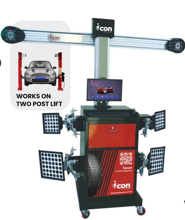
3D Wheel Alignment Machine – iSMART
750,000
–
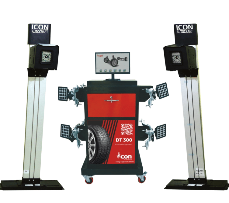
3D Wheel Alignment System (DT-300)
550,000
–
3D Wheel Alignment Machine (At Best Price)
400,000
395,000
NOTE:
Regular Price- reflects the original listed price.
Discounted Price- is shown where a promotional or sale price is currently offered.
All prices are subject to change; please confirm availability and final pricing with Icon Autocraft Pvt. Ltd.
Conclusion (Part A)
A 3D Wheel Alignment Machine is more than just a piece of equipment; it’s a strategic investment in your workshop's future. By providing unparalleled accuracy, reducing service time, and enhancing customer satisfaction, it elevates the quality of your service to new heights. Whether you operate a high-volume service center, a specialized performance tuning shop, or an independent garage, upgrading to a 3D wheel alignment system is the smartest move you can make to stay ahead in the competitive automotive industry.
Ready to Transform Your Workshop?
Reach out to Icon Autocraft Pvt. Ltd. today and experience the next level of automotive servicing with India’s best 3D wheel alignment solutions.
Pro Tip: For maximum uptime and longevity, schedule regular maintenance checks and use high-quality, manufacturer-approved components. Proper care ensures your 3D wheel alignment machine remains a key revenue driver for years to come.
PART B: 3D Wheel Alignment Using Computer Vision & Optimization
Introduction (Part B)
Proper wheel alignment is crucial for any vehicle’s performance, safety, and tire longevity. When wheels are misaligned, drivers often notice:
Uneven tire wear: leading to premature and costly replacements.
Reduced steering precision: causing the car to drift to one side.
Decreased fuel efficiency: due to higher rolling resistance.
Traditionally, alignment checks involve manual measurements and mechanical gauges, which can be time-consuming and susceptible to human error. Modern automotive service centers are increasingly adopting 3D Wheel Alignment systems that utilize stereo vision, image processing, and mathematical modeling to provide faster and more accurate results.
What Is a 3D Wheel Alignment System? (Part B)
A 3D wheel alignment system is designed to measure key angles of the wheel—camber, caster, and toe—all in three-dimensional space. It uses:
Stereo Vision: Two or more cameras capture images from different angles, providing depth (3D) information similar to human binocular vision.
Image Processing: Techniques like Gaussian blur, edge detection, and optical flow help isolate and track reflective markers placed on each wheel.
Mathematical Modeling: Methods such as least squares regression and Kalman filtering reduce noise and refine the measurement of wheel angles.
Real-Life Example
Imagine a busy service technician who needs to align multiple vehicles per day. With a 3D system:
Two cameras face the vehicle.
Reflective markers are attached to the wheels.
Within minutes, the system calculates the wheels’ angles and displays needed adjustments.
This setup dramatically reduces the room for human error and speeds up the alignment process.
Step-by-Step Methodology (Part B)
Below is a simplified breakdown of how a 3D Wheel Alignment system works, from image acquisition to displaying final alignment angles.
Image Acquisition & Feature Detection
Stereo Correspondence & 3D Reconstruction
Triangulation & 3D Position Calculation
Wheel Angle Calculation & Alignment Optimization
Angle Computation (Camber, Caster, Toe)
Results Display & User Interface
Let’s explore each step in more detail.
1. Image Acquisition & Feature Detection (Part B)
Goal: Capture clear, noise-free images of the reflective targets on each wheel.
Gaussian Blur: Used for smoothing out noise or glare from shop lights. If you have an overhead light causing bright specks on the marker, a blur (with a parameter like σ = 1.5) can help isolate the marker edges more effectively.
Sobel Edge Detection: After smoothing, the Sobel operator highlights marker boundaries by calculating gradients in the horizontal and vertical directions.
Real-Life Example
A wheel marker might appear 50 pixels wide on the image. Sobel detection clearly outlines this area, making it easier for the system to track.
2. Stereo Correspondence & 3D Reconstruction (Part B)
Goal: Replicate binocular vision to determine depth (distance) to each marker.
Two cameras separated by a known baseline (B) capture the same target from slightly different viewpoints.
The disparity (d) is the difference in a target’s horizontal position between the two images.
Depth (Z) is computed using the formula: Z = (f * B) / d
Real-Life Example
If B = 0.2 m, f = 800 (in pixel units), and d = 40 pixels, then:
Z = (800 * 0.2) / 40 = 4 meters
This tells the technician that the wheel marker is 4 meters away from the cameras—handy in a large workshop.
3. Triangulation & 3D Position Calculation (Part B)
Goal: Convert the depth information into x, y, and z coordinates for each wheel marker.
Once Z is known, you can solve for X and Y using:
X = (x1 * Z) / f
Y = (y1 * Z) / f
These coordinates place the wheel in a 3D reference system relative to the cameras.
Real-Life Example
If x1 = 400 px, Z = 4 m, and f = 800 px:
X = (400 * 4) / 800 = 2 meters
Hence, the marker is 2 meters away from the camera’s center line.
4. Wheel Angle Calculation & Alignment Optimization (Part B)
Goal: Determine the wheel angles (camber, caster, toe) and filter measurement errors.
Least Squares Regression:
Used to “smooth out” multiple data points of wheel orientation.
A best-fit line or plane is found to represent the wheel’s position, reducing random measurement noise.
Kalman Filtering:
Real-time estimation technique.
Even if a technician briefly blocks the marker, the Kalman filter predicts the wheel’s angles based on past data until new readings are available.
5. Angle Computation (Camber, Caster, Toe) (Part B)
Camber (θc): Tilt of the wheel from vertical. Negative camber means the top of the wheel leans inward.
provides a robust, efficient, and user-friendly approach to vehicle wheel alignment. As vehicles become increasingly sophisticated, and time is at a premium in modern service centers, the precision, speed, and consistency offered by 3D alignment solutions are more relevant than ever.
Appendix: A Closer Look at Gaussian Blur (Part B)
A common tool in image processing for noise reduction is the Gaussian blur, defined as:
G(x, y) = (1 / (2πσ²)) * exp(-(x² + y²) / (2σ²))
σ (Sigma): Determines how wide the blur is. Larger σ means more smoothing.
Normalization: Ensures total sum of the filter equals 1, maintaining image brightness.
Implementation: Generate a Gaussian kernel (often of size 6σ + 1) and convolve it with the input image.
Practical Example
In an auto shop, if reflective markers produce distracting glare, applying a Gaussian blur with σ = 2.0 can effectively smooth out bright spots, making feature detection more reliable.
References (Part B)
Automotive Manuals & OEM Specifications
Camera Calibration and 3D Reconstruction, OpenCV Documentation
Hartley, R., & Zisserman, A. (2004). Multiple View Geometry in Computer Vision.
Kalman, R.E. (1960). A New Approach to Linear Filtering and Prediction Problems.
PART C: ICON Encore Gold 3D Wheel Alignment Machine – Operational Manual
1. Introduction (Part C)
Thank you for choosing the ICON Encore Gold 3D Wheel Alignment Machine. This state-of-the-art aligner is designed to measure and adjust critical wheel parameters—such as toe-in, camber, caster, and more—ensuring optimal vehicle steering performance and minimal tire wear.
Key Features
3D digital imaging with high-resolution cameras.
No electronic components in the targets (passive targets).
Large field of view for various vehicle sizes.
Automated measurement processes and easy-to-use software.
Integrated vehicle database with 20,000+ models.
IMPORTANT: Please read this manual thoroughly before operating the machine. Misuse or failure to follow instructions may void your warranty and could result in machine malfunction, personal injury, or equipment damage.
2. Precautions (Part C)
Please read this user manual thoroughly before operating the ENCORE GOLD.
The Aligner is intended for use by properly trained, skilled automotive technicians. The safety messages presented in this section and throughout the manual are reminders to exercise extreme care.
The operator must have knowledge of computer application and basic theory of wheel alignment.
The power voltage of ENCORE GOLD is AC220V ±10, 50HZ.
The three-terminal sockets must be used, and the earth terminal must be well grounded.
If the power voltage is not stable, please use CVT & UPS.
Don’t place the ENCORE GOLD on a vibrated object or an opaque surface.
Avoid direct sunlight and moisture. Keep ENCORE GOLD away from outside infrared rays from directly lighting the targets and reflecting to the cameras.
Avoid blocking the light ways from the targets to cameras when the instrument is working.
Turn off the power after operation. Check all bolts and parts after maintenance.
Do not damage the targets when using and storing. Keep the surface of targets clean. Use a soft cloth with neutral detergent to wipe the surface lightly.
The wire inside the cabinet and the camera posts are connected compactly. Don’t move them after installation.
Do not move or wobble the camera post during or after use.
Do not disassemble the machine without approval of the supplier. Unauthorized disassembly will void the warranty.
Keep the surface of the camera lens clean; do not impact them. Use lens paper to wipe the surface of the lens.
Cut off all power supply after using.
3. Safety Instructions (Part C)
Risk of electrical shock
Do not operate equipment with a damaged power cord or if the equipment has been dropped or damaged.
Do not expose the equipment to rain. Do not use on wet surfaces.
If an extension cord is necessary, use one with a current rating equal to or greater than that of the equipment.
Do not remove or bypass grounding pin.
Do not open any part of the console other than noted areas.
Turn power switch off and unplug the unit before servicing.
Risk of crushing
Leave automatic transmission in park or manual transmission in gear unless equipment operation steps require vehicle in neutral.
Apply parking brake unless wheel movement is required.
Use wheel chocks whenever vehicle is positioned on the lift.
Follow rack or lift manufacturer’s safety recommendations when lifting a vehicle.
Note: There are many variations in procedures, techniques, tools, and parts for servicing vehicles. It is the automotive technician’s responsibility to be knowledgeable of the vehicle to be aligned and follow proper service methods.
4. Specifications (Part C)
Parameters
Range
Toe in
±20° (Accuracy 2')
Camber
±10° to ±25° (Accuracy 2')
Caster
±15° to ±30° (Accuracy 4 to 6')
KPI
±15° to ±30° (Accuracy 5 to 6')
Setback
±5° (Accuracy ± 2')
SAI
±20°
Individual Toe
0.01°
Note: 1 Prime(')= 1°/60 Minutes
Surrounding Requirements
Ambient temperature: 0~+60°C
Operating humidity: 70%
Light requirement: No direct strong lights does not irradiate the targets and cameras
5. Machine Overview (Part C)
ENCORE GOLD mainly consists of eight components:
Control unit (main unit)
Cameras
Posts
Wheel clamps
Targets
Communication cables
Mechanical turntables
Steering wheel holder
Control unit: Consists of computer system, interface circuit system, power supply assembly, monitor, keyboard, mouse, printer, and image collector.
Cameras & Posts: The machine has 2 cameras for capturing images of 4 targets on the wheels.
Communication cables: 2 signal cables + 2 power supply cables.
Wheel clamps & Targets: 4 target-clamp assemblies; correct fastening is essential for accurate results.
Mechanical turntable: Placed under the front wheels on the lift.
Steering wheel holder: Locks steering wheel during measurement per software prompts.
6. Basic Alignment Procedures (Part C)
Gather information from the vehicle owner regarding any symptoms of misalignment.
Perform a test drive to verify the complaint.
Place vehicle on the alignment lift; center it on the lift and turntables.
Inspect the tires for any signs of abnormal wear. Check suspension components, tire pressure, and ride height.
Mount measuring targets on the vehicle’s wheels. Use safety straps to secure.
Choose the proper wizard procedure for the vehicle.
Perform rollback compensation to eliminate measurement errors due to wheel run-out.
Measure caster, camber, and toe.
Determine necessary corrections; reference your alignment data and the vehicle’s OEM specs.
Adjust angles in the typical order:
Rear camber
Rear toe
Front caster
Front camber
Front toe
Re-center the steering wheel and perform a final check.
Print the results for the customer and keep a copy for records.
Test drive to verify proper alignment.
7. Operation Instructions (Part C)
Mounting Targets and Wheel Clamps
Install the wheel clamp-target assembly on the wheel. Lock the clamp firmly with the knob.
Ensure each clamp claw is fixed on the rim edge properly and securely.
Use safety belts/straps to avoid accidental clamp falls.
Large targets usually go on rear wheels; small targets on front wheels.
Initial Setup and Software Navigation
Connect the power cable (AC 220V ±10%, 50Hz) and switch on the main power. Boot the computer.
When the software loads, you’ll see the main menu with options (Standard Measurement, Quick Measurement, Additional Measurement, System Management, Print, Help, Exit).
Select Standard Measurement to begin. Choose the vehicle make and model from the database, or enter details manually if not listed.
Enter additional details such as customer info, license number, tire diameter (if linear toe measurement is required), and so on.
Rolling Run-Out Compensation (ROC)
Lock the steering wheel in the straight-ahead position. Release the brake pedal if necessary.
Push or pull the vehicle ~30 cm forward or backward as the on-screen indicators instruct.
The system automatically compensates for any wheel clamp or rim run-out.
A “red target” status indicates blocked light or an image-capture issue.
Note: While you can skip ROC if the wheel mounting is highly accurate, it is generally recommended for best precision.
Caster and SAI Swing
Ensure the steering wheel is centered (FL toe = FR toe).
Turn the steering wheel about 15° to one side per software prompts. Wait for the indicator to turn green.
Repeat for the opposite side. The system then calculates caster and Steering Axis Inclination (KPI/SAI).
Center the steering wheel again. Measurement results will show automatically.
Caution: Lock the hand brake and install a brake pedal depressor before measuring.
Front and Rear Axle Measurement
When measuring front and rear axles, the following additional details are crucial:
Alignment Tolerances: Consult OEM specifications for acceptable ranges in camber, caster, and toe on both axles. Rear misalignment can affect the front geometry, so ensure rear angles are correct before finalizing the front.
Setback Adjustments: Check if there is any difference in wheelbase length on either side of the vehicle. If setback exceeds recommended specs, inspect for possible frame damage or suspension misalignment.
Thrust Angle: The angle between the rear axle’s centerline and the vehicle’s centerline. Ensure thrust angle is within OEM specs to avoid “dog tracking” and uneven tire wear.
Adjusting rear alignment first ensures the vehicle’s thrust line and rear geometry are correct, which then allows for precise front-end corrections. This sequence minimizes steering wheel offset and overall misalignment issues.
Adjustments and Lift-Up Procedure
Sometimes lifting the vehicle is required for easier adjustment. The system provides a Lift-Up function:
Click the Lift-Up button; raise the vehicle.
The system compensates for inclinometer offsets automatically.
After adjustment, lower the vehicle and finalize alignment.
Printing Reports
Print Report can print and save alignment data.
Client information: Not entered directly on this screen; use [Client Management].
Vehicle information: Displayed if the model is selected.
Operator: Choose from [User information].
Click Save to store alignment data; click Print to print it.
Note: The main interface’s Print function can print all saved records; the Print Report button here only prints the current alignment.
Maintenance
Computer: Keep away from freezing, wet conditions, or direct sunlight. Do not frequently switch on/off or move during operation.
Wheel Clamp & Target: Clean and lubricate as needed. Targets are key components; do not damage or disassemble.
Printer: Install correct drivers. Replace ink when prints become unclear.
Posts & Signal Cables: Do not move or wobble the camera post after installation. Prevent direct sunlight from hitting targets/cameras.
Turntables: Insert lock pin to avoid sliding. Remove when performing alignment.
Common Reminders and Tips
Always Zero the Steering Wheel: A crooked steering wheel is a frequent complaint.
Follow Adjustment Order: Rear camber → rear toe → front caster → front camber → front toe.
Record Before & After Data: Provides transparency and future reference.
Protect from Infrared Interference: Use shading if strong sunlight or overhead IR is present.
Remember the Steps:
Perform run-out compensation if needed.
Lock steering wheel and brake as appropriate.
Check and adjust rear camber and toe.
Proceed to front caster, camber, and toe.
Finalize the steering wheel center before printing the final report.
Following these guidelines during Front and Rear Axle Measurement helps maintain consistency and accuracy, ensuring the final wheel alignment meets the manufacturer’s specifications and provides the best handling performance and tire longevity.
#TOP10 Frequently Asked Questions!
It is designed to provide quick and easy access to information that can assist you in resolving some of the expected issues or concerns.
A wheel alignment machine adjusts wheel angles to ensure they are parallel to each other and perpendicular to the ground. This improves vehicle handling, performance, and safety. The machine has a computer, sensors, clamps, and turntables that collect wheel position and orientation data. The computer compares this data with the manufacturer’s specifications and guides the technician on how to correct any misalignment.
A wheel alignment machine’s price depends on the brand, features, accuracy, and warranty. It can cost between 3.5 to 12 lakhs based on the quality and specs. Higher-end machines offer more functionality like wireless sensors, 3D imaging, and auto-calibration. Lower-end machines may provide reliable results but have fewer features. Before making a purchase, it is important to compare various models and options. Alternatively, you can speak with our experts for personalized recommendations.
The machine comprises a lift, console, sensors, and targets. The sensors measure the angles of camber, caster, toe, and thrust, and the targets reflect the laser beams from the sensors. The machine calculates and adjusts the wheels according to the manufacturer’s specifications. Finally, it prints out a report for the customer.
The 3D wheel aligner is an incredibly precise tool for aligning wheels, utilizing advanced cameras and sensors to measure the wheel angles and displaying the results with pinpoint accuracy on a computer screen. With its ability to detect even the slightest deviations from optimal alignment, it provides the most precise adjustments possible. Furthermore, the 3D wheel aligner is renowned for its speed, simplicity, and versatility, making it an ideal choice for a wide range of vehicles.
Selecting the right manufacturer for your automotive business is a critical decision that demands careful consideration. To ensure that you make an informed choice, it is vital to weigh various crucial factors like your business’s specific needs, the level of precision required, the types of vehicles serviced, ongoing technical support, and overall budget. As a top-tier automotive equipment manufacturer, ICON Autocraft Pvt. Ltd. has established a reputation for excellence in the industry. However, it is important to note that the perfect manufacturer for you may vary based on your unique needs and preferences.
To use an alignment machine, you need to follow these steps:
1. Park on a level surface and turn off the engine. 2. Attach sensors to each wheel per machine instructions. 3. Connect sensors to the computer and enter vehicle info. 4. Start alignment test and follow on-screen prompts. 5. Adjust wheels as needed using machine recommendations. 6. Finish the test and remove the sensors. Print results if desired.
If you’d like a more detailed explanation, we’ve got you covered! Our blog has plenty of helpful information. To read, simply – click here!
A new wheel alignment machine may be needed when the old one is outdated, damaged, or inaccurate. Some signs that indicate a need for a new wheel alignment machine are:
Inability to perform alignments on newer vehicle models with advanced features such as adaptive steering or suspension systems.
Inconsistent or erroneous readings that don’t match the manufacturer’s specifications or visual inspection.
The machine requires frequent calibration, maintenance, or repairs that are costly or time-consuming.
Low capacity, speed, or performance impacting productivity and profitability of your service.
Are you in search of a wheel alignment machine? Wondering whether to go for a new or secondhand one? Take a moment to consider the pros and cons before making a decision. A used machine may seem like a cost-effective option, but it could have wear and tear, calibration issues, or outdated features. On the other hand, a new machine can offer better accuracy, performance, and warranty. Make the most of your investment by choosing a machine that aligns with your goals and aspirations.
Our Pan-Asian network is the ultimate destination for sales, services, and safety analysis, backed by a team of expertly trained engineers. With over 2500 garages placing their trust in our products, we provide unbeatable value for money. Rest assured, we are always at the forefront of the latest technology, and we take pride in our ability to adapt to changing times. You can confidently rely on us for all your automobile-related needs.